Class documentation of Concepts
Detailed Description
The module geometry contains classes to describe meshes (topology, coordinates, cells etc.), the list below shows the most important ones.
All header files declaring classes for the geometry can be found in the subdirectory geometry.

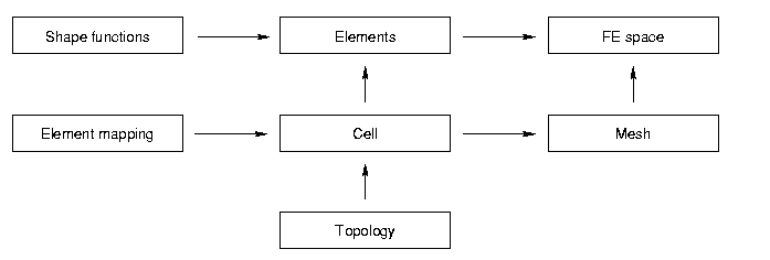
The geometry of the domain of interest consists of the topology (vertices, edges etc. and how they are connected) of the elements and the element mappings (introduces the coordinates). A topological element of the mesh together with its element mapping forms a cell of the mesh. All cells together form the mesh itself.
Topology
The classes which describe the topology of a mesh are all declared in the file topology.hh. The basic class for the topology is concepts::Connector (refer to the respective pages for more detailed documentation).
Also part of the topology is how elements have to be subdivided to reach a higher level of refinement. Eg. a vertex is not subdivided but simply copied. An edge is cut into two new edges. A triangle or a quadrilateral are cut into four new. More on subdivisions can be found in the description of concepts::QuadSubdivision, concepts::Quad2dSubdivision, concepts::HexSubdivision and concepts::Hex3dSubdivision.
Element Mapping
An element mapping maps a reference element to the physical element. The application operator of the class maps a point from the reference element to the physical element.
The following classes are declared: concepts::Map1d, concepts::Map2d, concepts::Map3d.
Cell
The cells combine the topology and the element maps. They will finally be assembled to a mesh. The base class for all cells is concepts::Cell.
Mesh
A mesh is simply several cells together with a public subclass acting as some sort of scanner for the mesh. The mesh holds the vertices, edges, triangles or quadrilaterals and cells of the original mesh which is built in the constructor. There are quite a few examples which are already implemented such as the unit disk, or a square.
The base class for all meshes is concepts::Mesh.
HOWTO Implement a New Mesh
I describe the procedure to implement a new mesh with the example of the unit square [0, 1]2. More complex examples can be found in the meshes tutorial. Most meshes do not have to be programmed though, they can be imported from a file using concepts::Import2dMesh or concepts::Import3dMesh.
Derive a New Class
In order to implement a new mesh one needs to derive a new class from one of the children of concepts::Mesh. In our example this would be the class Quadrat derived from concepts::Mesh2.
The easiest way to achieve this is to copy the definition of an existing mesh.
New Topology and Geometry
Besides changing the declaration of the member (triangles, cells etc.) the constructor and the destructor have to be changed.
-
The constructor of Quadrat looks like this: vtx_[0] = new Vertex;vtx_[1] = new Vertex;vtx_[2] = new Vertex;vtx_[3] = new Vertex;edg_[0] = new Edge(*vtx_[0], *vtx_[1]);edg_[1] = new Edge(*vtx_[1], *vtx_[2]);edg_[2] = new Edge(*vtx_[2], *vtx_[3]);edg_[3] = new Edge(*vtx_[3], *vtx_[0]);quad_[0] = new Quad(*edg_[0], *edg_[1], *edg_[2], *edg_[3]);cell_[0] = new Quad2d(*quad_[0],MapQuad2d("(x, y)", 1.0, 1.0));
-
The destructor of Quadrat looks like this: for(uint l = 1; l--;)delete cell_[l];for(uint k = 1; k--;)delete quad_[k];for(uint j = 4; j--;)delete edg_[j];for(uint i = 4; i--;)delete vtx_[i];
For more complex geometries, one has to be very careful about the orientation of the edges in the mesh as a whole and in the different cells.
Generated on Wed Sep 13 2023 21:06:25 for Concepts by
